
ANZINE : CAE 기술 매거진
이전 ANZINE Home Case Study


[Global] A world on water
- Livio Furlan
- EnginSoft
- l.furlan@enginsoft.com
A world on water
Livio Furlan, EnginSoft
Published in Futurities Year 21 n°1 by EnginSoft
■ Abstract
바다는 열에너지의 잠재적 원천으로 주목받기 시작했으며, 해저 퇴적물은 풍부한 광물 자원과 탄화수소의 보고(寶庫)입니다. 현재 해양 석유와 가스는 전 세계 에너지 수요의 약 3분의 1을 차지하고 있습니다. 이러한 흐름에 발맞춰 해양 건설 산업은 해양 자원 개발을 위한 구조물 설치에 주력해왔습니다. 막대한 경제적 가치를 지닌 해양 석유 및 가스 산업은 관련 기술의 빠른 발전을 이끌었고, 이를 통해 인간의 창의성과 기술력은 극한의 환경에서도 놀라운 공학적 성과를 이루어냈습니다. 본 기고에서는 그 대표적인 두 가지 사례를 통해 이를 살펴보고자 합니다.
바다 위에 작은 ‘세계’를 세우는 일은 과학적이고 체계적인 접근 없이는 불가능합니다. 정밀하고 안전한 설계를 위해서는 끊임없는 연구와 실천, 끈기, 신중함, 열정, 그리고 창의성이 조화를 이루어야 합니다. 이러한 요소들이 균형을 이룰 때 비로소 하나의 구조물이 완성되는 진정한 ‘성공’이 실현될 수 있을 것입니다.
오늘날 인공지능이 인간을 대체할 수 있다는 전망이 나오고 있지만, 여전히 새로운 아이디어를 구상하고 실현하는 일은 인간의 몫입니다. 해양 설계가 이루어질 환경과 조건을 철저히 이해하는 전문 팀이 구성된다면, 지금까지 인류가 그래왔듯, 다양한 위험 요소와 복합적인 상황에 효과적으로 대응할 수 있을 것입니다.
There is a wide range of offshore and marine structures each of which is suitable for specific situations and, in the case of hydrocarbon reservoir exploitation, this is determined by the extent of the reservoirs themselves, their “productive” capacity, the depth of the seabed, and the weather and environmental conditions.
Fixed structures consist of an underwater part (steel jacket) fixed to the seabed with foundation piles, and an above-water part (deck) housing the drilling and production equipment as well as the modules required to operate the platform.
The jacket is made of steel tubular elements and is the part of the structure most directly affected by the forces of wave action and currents; it is also designed to withstand loads from the deck, as well as the stresses induced by exceptional events such as earthquakes, the impact of supply vessels, and/or icebergs. The deck is the operative area and contains the equipment, apparatus, and modules; it houses both the productive life of the platform and the rest area between shifts.
It is important to note that fixed offshore structures are not only used for extracting oil and/or gas deposits. They are also used in the green energy sector (offshore wind farms) to house wind turbines and/or the power plants that transform the energy produced.
In addition to steel lattice jackets, fixed platforms can be constructed of concrete caissons (e.g. the Condeep concept, see Fig. 1), which not only store the product extracted from the field but also provide the hydrostatic buoyancy needed to keep the structure afloat during transport (towing) from the construction dock to the installation site.
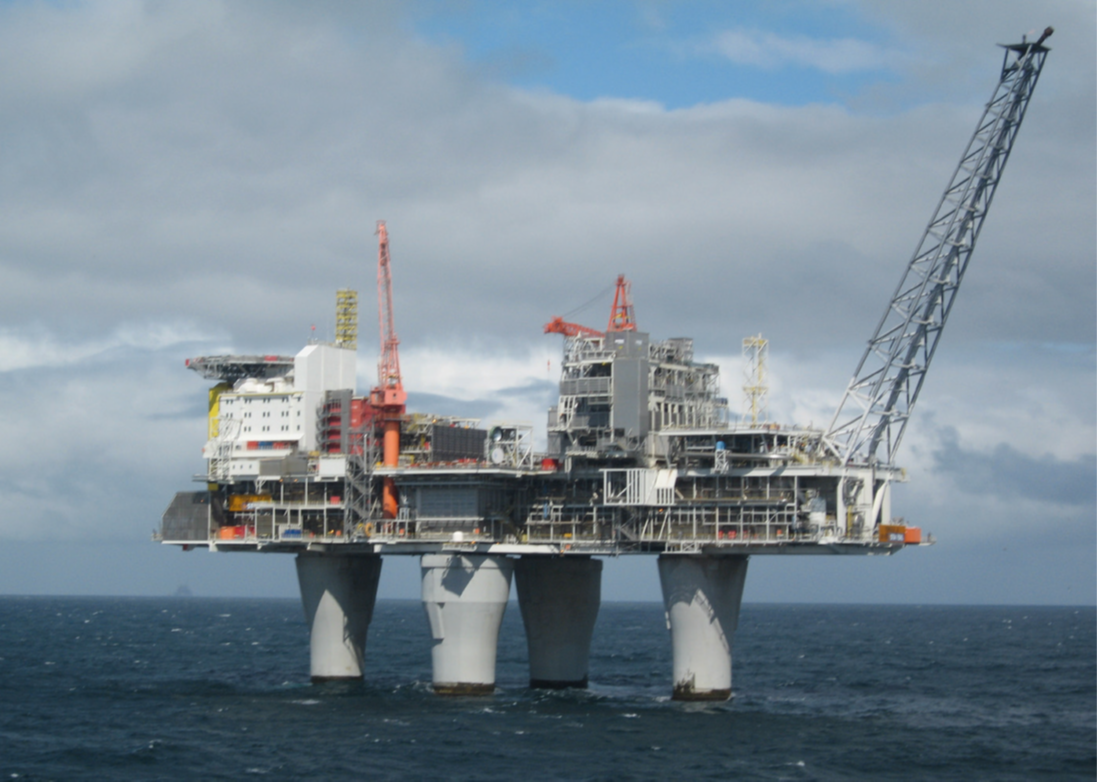
Fig. 1. The Condeep platform Troll A. (credit: https://commons.wikimedia.org/wiki/File:Troll_A_Platform.jpg)
Typically, tension rods are made up of several segments. The upper part consists of a cable or rope that acts as a rigid spring in moderate sea conditions. The lower part consists of a heavy chain with clump weights attached to it, which are lifted from the seabed in rough sea conditions, thus activating a "soft" spring-like behaviour that makes the tower more compliant.
Floating, production, storage and offloading (FPSO) solutions are used in fields at great depths, for instance where is both too expensive and difficult to use fixed structures, as well as in marginal fields, i.e. those with limited reserves. Essentially, these are floating units, anchored to the seabed by mooring lines that absorb the weather-induced actions (wave, current, wind). The unit receives fluids (crude oil, water, and a host of other things) through the risers from the wellheads located on the seabed.
The FSRU (Floating Storage and Regasification Unit) is sister to the FPSO solution.
A FSRU is a naval unit used as an offshore terminal at which vessels can unload LNG (liquefied natural gas). Once transferred to the FSRU, the liquid product is regasified (hence the generic term regasifier) and fed into the national distribution network.
Another floating moored structure is the tension leg platform (TLP), a vertically moored floating structure typically used for the offshore production of oil or gas but also for green energy (using offshore wind turbines installed on TLPs). This is particularly suitable for waters with depths of between 300 and 1,500 metres. The platform is permanently moored by tethers or tendons grouped in each corner of the structure's hull.
■ Standards and rules
The design, transport, installation, survey, and maintenance phases of offshore structures are governed by specific rules and/or recommended practices that are laid down by certification bodies and/or internationally recognized associations, including API (American Petroleum Institute), DNV (Det Norske Veritas), ABS (America Bureau of Shipping), and BV (Bureau Veritas). But how is the safety of structures determined?
■ Calculation and verification approaches – comparison between allowable stresses (ASD) and limit states (ULS)
The first calculation/verification method to be introduced in the standards was Allowable Stress Design (ASD). It is based on purely deterministic criteria, i.e. it assumes that all loads considered cannot exceed their nominal value.
The same assumption also applies to the value of material strengths, which is calculated by dividing the characteristic stress (which can be the yield stress) by an appropriate safety coefficient. The limit state method, also known as Ultimate Limit State (ULS), Accidental Limit State (ALS), and Serviceability Limit State (SLS), was introduced after the ASD method and is semi-probabilistic in nature. The applied actions are considered random and are subject to procedures of combination and factoring with partial coefficients that depend on the probability of occurrence and contemporaneity of the stressing phenomena. These coefficients increase the characteristic (nominal) stresses to obtain the design stresses (Fd).
The characteristic resistances are also treated in random terms, but the coefficients (which are dependent on the importance and reliability assigned to a structural component or welded and/or bolted connection) reduce their values to obtain the design resistances (Rd).
The relationship to be respected therefore becomes:
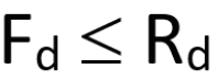
From this standpoint, we could classify the semi-probabilistic method as level I in that it is only compares the scalars (the calculation stress, Fd, and the calculation resistance, Rd), unlike the probabilistic level II and III methods (which actually determine the probability of failure and/or collapse).
■ Engineering offshore structures
Irrespective of whether they are intended to exploit oil and/or gas fields (even in difficult conditions, e.g. the North Sea) or to produce green energy (offshore wind farms), offshore structures require specific studies and research into design and construction solutions that allow for reliable and safe construction over time.
When applying structural engineering to this sector, engineers must include advanced virtual prototyping, which combines theories and studies on wave motion (and the actions resulting from this) and specialized numerical simulation, which in this sector is highly specific and is therefore generally entrusted to calculation software expressly developed to investigate the behaviour of submerged structures that are subject to hydrodynamic forces when installed.
Sticking to the context of immersed fixed lattice structures (jackets), the wave forces can be calculated by adopting Morison's equation, which sums two force components, i.e. a drag force and an inertia force, as shown below:
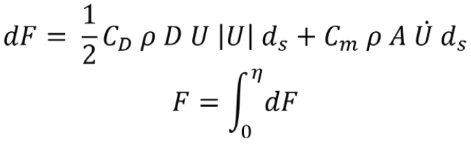
where:
- · F is the total force in the direction of the water velocity and acceleration,
- · η is the instantaneous water level,
- · ρ is the mass density of water,
- · U is the instantaneous velocity of the water normal to the axis of the member (component of vector sum of u – horizontal and v – vertical water particle velocity normal to the member) – if a steady current is present, it should be added vectorially to it,
- · U ? is the instantaneous acceleration of the water normal to the axis of the member (component of vector sum of u – horizontal and v – vertical water particle acceleration normal to the member),
- · D is the width or the diameter of the section,
- · A is the cross-sectional area of the section,
- · CD is the drag coefficient,
- · Cm is the inertia or mass coefficient (Cm=1+Ca where Ca is the added mass coefficient).
Instantaneous velocities and accelerations (wave kinematics) are calculated on the basis of wave theories such as linear (Airy), Stokes 3rd and 5th order, solitary wave, etc. In addition, Morison's equation applies in cases where the diameter of the membrane struck by the wave is not greater than 0.2 times the length of the wave; otherwise, the effects of diffraction and the Froude-Krylov forces must be considered.
The standard form of the Morison equation above assumes that the structure subject to the wave forces is rigid. However, if the structure has its own dynamic response or is part of a floating body, the structure's induced motion may be significant as compared to the wave's orbital velocities and accelerations. In such a case, the "dynamic" form of the equation becomes:
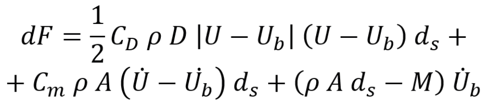
where:
- · Ub is the velocity of the incremental section of the structural member,
- · U’ b is the corresponding acceleration of the section,
- · M is the mass of the section,
- · and the other symbols are defined above.
Morison's equation is applied to each member of the structure to determine the distribution of hydrodynamic forces affecting the structure for each of the monochromatic waves (year wave, 100-year storm wave, etc.) foreseen in the design. The wave profile and its orbital velocities and accelerations vary according to space and time. It is therefore necessary to identify the maximum position, i.e. the position of the wave in relation to the structure for which the value of the overall hydrodynamic force (base shear load) is highest.
For fixed structures, this is achieved by setting up a “hydrodynamic” numerical model of the structure and passing the wave through it with an adequate number of advancing steps to effectively capture the relative wave-structure position that returns the maximum total shear at the base. The structure's response to the design conditions is determined on the basis of the distribution of hydrodynamic actions associated with the maximum total shear load condition.
To this end a beam-type finite-element model of the jacket structure is developed, complete with foundation piles, and their interaction with the ground simulated by means of p-y and t-z curves, and of the deck structure with the load distribution associated with the equipment, modules, installations, etc. depending on the level of representation required. Detailed finite element modelling studies via shell and solid elements are left for later.
The hydrodynamic forces calculated using the Morison equation for each of the design conditions and for each of the members are added to the finite element model. This results in a virtual “prototype” of the real system that is solved with typical numerical methods of the finite element approach, and which delivers the response of the structure in terms of nodal displacements and stress parameters on the members and foundation piles with sufficient reliability.
■ Code checks
Regulatory verifications are performed on the identified structural geometries to give the design choices consistency and to locate any weak areas:
- · resistance check (also called yield check),
- · buckling check,
- · combined yield and buckling check,
- · hydrostatic collapse check,
- · punching shear check (a typical check of tubular knots).
The yield check of a structural element is performed to assess whether the element itself is subject to acceptable stress levels. The check is performed using a yield interaction equation which is defined according to the verification approach adopted: ASD or ULS (see above).
The result generated by verification represents a utilization factor which is the inverse of the safety factor: if the factor is less than 1.0, the member is classified as safe; if the factor is greater than 1.0, the member is classified as unsafe and requires either local or extensive modifications to restore safety.
The yield check is generally performed at both ends and at the midpoint of a member to account for the way the members are subject to stress. However, there may be cases where it is necessary to define additional verification positions along the element to be checked.
The buckling check of a structural element is conducted to assess potential failure through instability in the elastic equilibrium of the element itself when subjected to axial load and bending moments. These are calculated in two orthogonal planes that generally coincide with the brace-chord plane (in-plane-bending) and with the plane orthogonal to it (out-of-plane-bending). The failure check is executed using a stability interaction equation which provides a utilization factor, like the yield check.
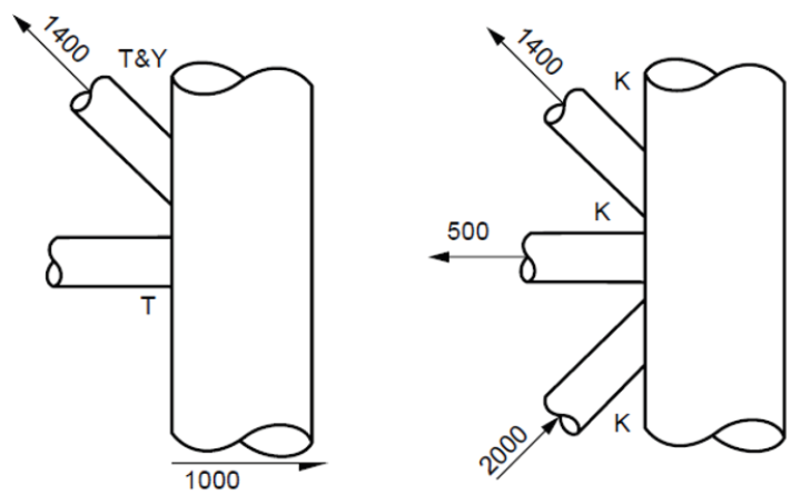
Fig.2 Joint behaviour – Y&T on the left, K on the right (from API RP 2A).
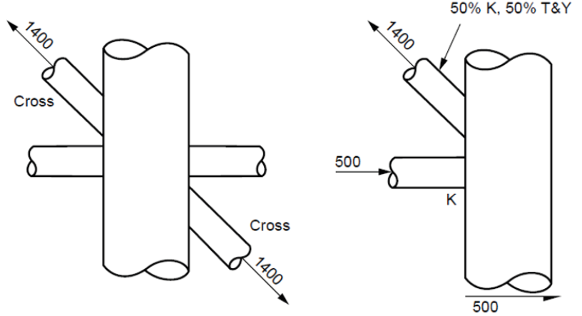
Fig.3. Joint behaviour – X on the left, mixed on the right (from API RP 2A).
Jacket members, which are made of circular tubular profiles, are generally watertight. They may, therefore, experience collapsing phenomena from hydrostatic pressure buckling (hoop stress) particularly at great depths. These effects are combined with the results of the axial and bending stresses along the members. A hydrostatic collapse check is then performed that combines the effect of hydrostatic pressure with the effects of other stresses and includes a check of the elastic instability of the generic member. Here again the verification yields a utilization factor to assess each element’s level of safety.
The elements of the jacket, whether leg/chord or brace, are made of hollow tubular profiles. A brace is the element that is headed over the through member, which is called a chord (or leg when referring to the jacket legs). A punching shear check of the chords must be conducted at the tubular brace-chord interface/connection.
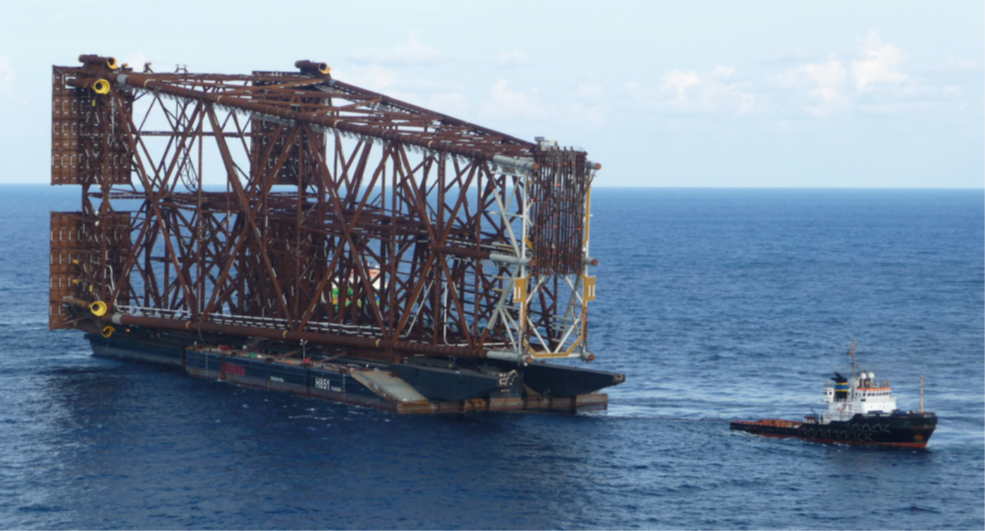
Tamar jacket on barge H851 with President Hubert on main bridle. (credit: https://commons.wikimedia.org/wiki/ File:Tamar_jacket_on_H851.JPG)
Tamar jacket launched from barge H851. (credit: https://commons.wikimedia.org/wiki/File:Tamar_jacket_ launch_2.JPG)
This verification assesses the local shear strength of the generic chord subject to the axial load and bending moments that act on the ends of the braces concurring to that chord.
As for the other verifications, this evaluation uses a punching shear interaction equation that yields a utilization factor that is defined by the sum of partial utilization factors, each of which is derived from the ratio between the actions present (axial load, in-plane bending and out-of-plane bending) and the corresponding permissible competence values calculated according to the chord-brace behaviour (Y&T behaviour, K behaviour, X behaviour, mixed behaviour, see Figs. 2 and 3).
In addition to the installed conditions (briefly described above) the jacket and deck structures are also affected by other important temporary conditions:
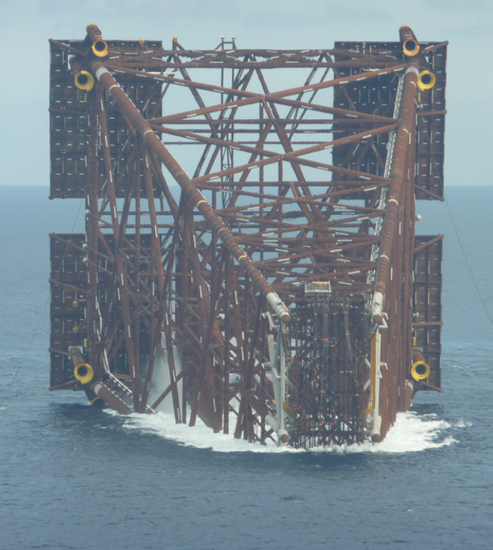
- · construction (e.g. roll-ups of the jacket facades/rows that are built in the horizontal plane and then pulled upright to create the structure to be achieved at the end of construction);
- · load-out (from construction site dock to transport vessel/ barge);
- · transport by sea from the construction site to the installation site;
- · launching of the jacket at the installation site and subsequent installation (instead of being “launched” into the water from the transport barge, the jacket can be lifted with cranes placed on naval vessels equipped for the purpose - e.g. Saipem's SSCV S7000 or Heerema’s SSCV Balder - and placed directly above the wells or placed on the waterline before being definitively installed);
- · lifting of the deck (already complete with modules, systems, equipment), again by means of cranes of adequate capacity placed on naval vessels equipped for the purpose, and its positioning on the Jacket which, in the meantime, will have been anchored to the seabed by means of foundation piles.
The structural behaviour of the jacket and deck have to be investigated for each of the temporary phases. This is done using suitable calculation models which consider specific aspects (e.g. for lifting this would include dynamic and skew effects) to determine the stresses for performing the code verifications listed above. Sometimes, in order to assist design and find support from numerical simulation, it may be necessary to develop detailed finite element models e.g. of tubular joints stiffened internally with rings, or of sleeve-leg regions in skirt piles (supported by appropriate portions of the foundation piles connected to the sleeves and, where necessary for the study, simulations of the grout), in addition to overall calculation models.
Finite element model analyses are also used intensively in the design and validation of the geometries of cast nodes for use in congested jacket regions (where the use of welded nodes becomes impossible) or in the case of deck and jackets nodes specifically dedicated to heavy lifting.
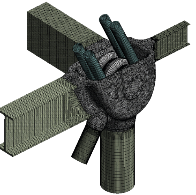
Fig. 4. Finite element model of a cast node complete with lifting ropes.
The example (Fig. 4) is that of the finite element model of one of the four cast nodes belonging to the structure of the RC002 Module (weighing approximately 95000 kN) installed on the Riser Platform of Johan Sverdrup Field (North Sea). The activity developed by EnginSoft in 2016 referred to the FEA calculation performed to validate the structural behavior of the node both for the lifting condition (heavy lifting) and for subsequent operating conditions.
In this regard it has to be said that, precisely with reference to the assessment of cast nodes strength resistance in heavy lifting condition, EnginSoft has implemented recognized and approved verification criteria based on the categorization of stresses and on the limitation of plastic strains for the regions characterized by (local) structural discontinuities.
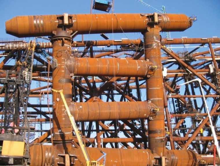
Fig.5. Sabratha jacket’s auxiliary buoyancy tanks (ABT). The ABT design was created in 2010.

Fig.6. Sabratha jacket in free floating condition after the launch.
An important activity which occurs when the jacket is launched concerns the design of the Auxiliary Buoyancy Tanks (ABT) shown in Fig. 5. These tanks provide the jacket with the necessary buoyancy to remain afloat immediately after launch and define the appropriate trajectory to allow it to self-upend i.e. float in a pseudo-vertical position at the end of the launch operation (see Fig. 6).
For jackets of limited weight and size, these are cylindrical tanks with torispherical or conical heads connected to the main legs of the jacket and subject to external pressure (in order to provide thrust, the tanks must be watertight and must therefore be verified against the risk of hydrostatic collapse) and the actions that develop during launch.
For larger jackets of correspondingly significant weight, on the other hand, these are “structures” within structures (see Fig. 5) that are still connected to the main legs of the jacket but positioned on the sides of the jacket itself. These are designed with specific methods that consider both the occurrence of external pressure and actions associated with the launch condition and particular geometric configurations, such as the one shown in Fig. 5, which was identified and made feasible by EnginSoft during design activity performed in 2010 for the ABT to be installed on the jacket of the Sabratha Offshore Platform for its launch and self-upending.
The lifting condition of ABTs during their removal is also important, particularly if the tanks are moved filled with water to speed up the operation: water has no weight in water but does have weight as soon as the tanks are lifted out of the water. The design/verification approach followed by EnginSoft for ABTs is the one proposed by "DNV RP C202 – Buckling Strength of Shells", which deals with the topic of stiffened cylinders subjected to external pressure superimposed on axial load, shear loads, bending moments and torque.
Dedicated finite element models with shell elements (see Fig. 7) especially of the “nodes”, i.e. the connections between cylindrical tank sections that can have diameters of 5.0– 6.0m (see Figs. 8 and 9), enabled the definition of a more reliable, less conservative and lighter design for the ABTs of the Sabratha jacket considering that the key, mandatory engineering objective for these ABTs was not to exceed a ratio of 0.25 of dry weight to thrust (the limit was respected as the ratio reached the value of 0.23).
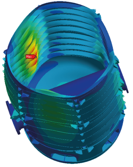
Fig.7. Example of buckling verification of a buoyancy tank.
Fig. 8. The nodal connection of the ring-stiffened cylinders of large auxiliary buoyancy tanks.
■ Fatigue
As previously mentioned, offshore structures, whether fixed or floating and/or moored, experience cyclic stresses induced mainly by wave motion. Therefore, it is essential as early as the design phase to foresee the fatigue response of submerged structures subject to varying loads, considering that stress concentrations facilitate the development of cracks and hence the achievement of local failure conditions which tends to alter the overall behaviour and can result in a chain of generalized collapse. The overall geometries of the brace-chord welded joints and the detailed geometries of the joint welds thus constitute the factors that influence the fatigue response of fixed latticework structures made up by of hollow circular sections. The overall geometries of the joints are considered by calculating the value of the stress concentration associated with the axial load (SCFa), the in-plane bending (SCFipb), and the out-of-plane bending (SCFopb) given the geometry of the specific joint and its behaviour (YT, K, X). The area involved in this calculation which is the zone that contains the brace-chord intersection curve is called the hot-spot region.

Fig. 9. P-formulation finite element model of the auxiliary buoyancy tanks at the region where the 5.0m diameter ring-stiffened cylinder connects with 5.6m diameter ring-stiffened cylinder.
The second factor (weld detail geometry) is accounted for by adopting a specific S/N curve for full penetration welded brace-chord joints.
SCFs can either be calculated on the basis of parametric formulae (Kuang, Wordsworth and Smedley, Efthymiou, Lloyd's Register) or determined by means of finite element models of adequate detail that are validated against parametric formulations on known cases.
By definition, an SCF is the factor by which the nominal stress due to axial force, pure in-plane bending, or pure out-of-plane bending must be multiplied at the stress point in question (located along the brace-chord intersection curve) to obtain the hot-spot stress to be used in the fatigue damage calculation. It is therefore necessary to first calculate the nominal stresses.
There are two main approaches to determine the accumulated damage in each structural region:
- · deterministic fatigue, in which the sea is represented by a series of monochromatic waves of given height and period and the associated number of occurrences for each wave and its incoming direction,
- · stochastic fatigue that accurately represents the energy content of the sea states (short-term sea state), each defined by significant height Hs, zero up-crossing period Tz, and probability of occurrence for each incoming direction.
In EnginSoft the deterministic approach to fatigue is applied (and has been applied multiple times) to structures (and components) that are dynamically insensitive or that are located in shallow to medium waters, where both the non-linearity of wave drag forces and the variable submersion of the structure (related only to water depth) are important. Since the method does not directly consider the energy content of sea states, judgment and experience are obviously necessary in selecting the number and height of discrete waves to include in the hydrodynamic analysis.
On the contrary, the stochastic fatigue approach is applied (and has been applied) to dynamically sensitive structures in medium-deep waters, where the non-linearity of the wave drag force is not as important compared to the overall values of the wave forces.
As mentioned, in the stochastic approach the energy content of each sea state is correctly represented, but the fluid-structure interaction must also be adequately considered, since in this approach the structure responds dynamically (albeit in the frequency domain). In fact, situations can occur where the frequencies (fi) of the incident waves are close to the fundamental natural frequencies of the structure, consequently requiring a reliable calculation of the resulting overall force while considering possible wave-cancellations or wave enhancement phenomena.
An example of a specific case of using the stochastic approach for evaluating fatigue damage is the work conducted by EnginSoft in 2019 on the cast components connecting the mooring lines of the Argos FPU (Mad Dog 2 field) to the anchoring suction piles installed in water approximately 1,400m deep.
The distribution of fatigue damage in the cast components welded to the suction piles was calculated by developing a finite element model of the component inserted in the suction pile (modelled in order to define adequate boundary conditions for that component).
Once the standard deviation σi of the maximum principal stress at each point of the component mesh for the ith couple of Hs,i , Tz,i inside the Wave Scatter Diagram was calculated, the following equation was used to calculate the damage:
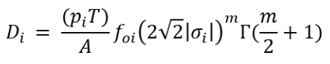
where:
- · Di is the fatigue damage for the ith sea state Wave Scatter Diagram,
- · T is the target fatigue life,
- · pi is the joint probability of Hs,i and Tz,i Wave Scatter Diagram,
- · foi is the zero upcrossing frequency of the stress response,
- · A and m are parameters of the different S/N curves considered for the non-welded and welded regions
- · Γ is the incomplete gamma function.
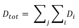
The sum of Di for each sea state i and for each incoming wave direction j provided the total damage Dtot at each point of the mooring component’s finite element mesh:
■ An epoch-making project
As the writer, and writing about offshore issues and structures, it is impossible to overlook an epoch-making project, which was proposed by Italian oil company ENI, and that represents a valid and interesting alternative to the project of the suspended bridge to cross the Strait of Messina between the Italian mainland and the island of Sicily.
The suggested concept consists of three independent tunnels (one for rail traffic, two for road traffic), approximately 6.2km long in water, with an almost elliptical section and of around 6.2km in length. The tunnels would be positioned at approximately 40m below the sea and anchored to the seabed at a maximum depth of 400–450m by means of stays attached to foundation templates fixed to the seabed by piles on one end and to collars installed around the elliptical segments of the tunnels on the other end. These three tunnels would form the three “Archimedes Bridges” (or tunnels in the riverbed) and would exploit Archimedes' principle according to which a body immersed in a fluid receives a bottom-up thrust equal to the weight of the fluid being moved. Since the installation site is characterized by high seismicity, it was imperative to thoroughly examine the structural response of the tunnel-system to seismic events, as well as to tidal currents. It was precisely because of the intensity of the tides that it was decided to move the installation position of the three tunnels with respect to that of the bridge. For this reason, the proposed bridge is approximately 3,600m long, while the tunnels would have been just over 1.7 times the length of the bridge.
EnginSoft's structural-offshore engineering team collaborated intensively with Tecnomare (now EniProgetti) on this specific project and, in particular, on problems of a dynamic/ seismic nature. It was the years 1992 and 1993, therefore more than 30 years ago, at the very beginning of the period in which numerical simulation – also thanks to EnginSoft's decisive contribution – began to play a decisive role in the development of complex systems engineering.

Fig. 10. Messina Strait Crossing – folding-fan solution for the bearing stays of the Archimedes Bridge (project developed throughout 1992 and 1993)
The collaboration resulted in the implementation of numerical models to assess the structural behaviour of tunnel-systems subject to hydrodynamic actions and to seismic accelerations. At the time, the latter were derived from the accelerations generated by the El Centro earthquake and were introduced into the models as imposed displacements obtained by double integration of the accelerations. At the same time, again with the aim of studying the seismic response from the geomechanical interaction of the head-tunnel with the ground, localized models were developed of the coastal regions to which the tunnel would be connected by means of large bellows.
After a series of studies, a so-called fan-shaped solution was devised (see Fig. 10), whereby groups of stays would be assembled precisely in a fan-shape. This was done to reduce the number of foundation templates to be installed on the sea floor and, most importantly, to provide the generic tunnel with as constant a vertical rigidity as possible along its axis to minimize the elastic curvature gradients and, therefore, bending gradients/peaks.
Furthermore, compared to the initial configuration characterized by stays placed on vertical planes with respect to the axis of the generic tunnel and frozen in 1987 after a first series of feasibility studies, the fan-shaped solution had lower natural frequencies (than those pertaining to the 1987 solution), meaning mitigation of the seismic response since the fan-shaped structure responded dynamically in areas of the spectrum characterized by lower acceleration values.
Time-domain analyses developed on one-dimensional finite element models (beams) that had been specifically implemented to accommodate the geometric nonlinearities (large deflections) mainly associated with the behaviour of anchor stays were used to determine the structure's response to both hydrodynamic actions and seismic imposed motion (in term of imposed displacements). These analyses progressively led to the identification and development of the fan-shaped stay configuration.
It should be noted that, at the time, beam models were intensively used to evaluate the seismic response of tunnel systems for two reasons: first, the limitations of computational capabilities required the development and fine-tuning of 'lightweight' models that were functional and compatible with the required representativeness; and second because unidimensional items have provided an adequate level of reliability in studies of overall behavior.

Fig. 11. Phenomenon of alternating vortex shedding. (credit: https://en.wikipedia.org/wiki/Vortex_shedding | Cesareo de La Rosa Siqueira)
Once post-processed with expertise and wisdom the beam-element models yielded the necessary results. Thereafter the required code verifications of strength and of dynamic stability (particularly for the stays which were actually tubular members) were conducted specifically considering the dynamic nature of seismic actions. To this end, a verification method was developed based on the Russian physicist V. V. Bolotin's treatment of the subject. The issue of vortex shedding on the stays was also addressed since the alternating frequency of vortex shedding in the fluid field can generate resonance phenomena with cross flow (CF) and in-line (IL) vibration – particularly if it is near the eigenfrequency of the cylindrical element, i.e. the stay (see Fig. 11) impacted by the fluid.
Finally, a feasibility study was conducted of the foundation templates and of the connections between the heads of the stays and the templates themselves using detailed finite elements.
■ Case study: an FPSO mooring system
In offshore oil production involving deepwater fields, for which fixed structure or pipeline installations are technically prohibitive, or in marginal fields whose short operational life makes it economically unprofitable to use these installations, FPSO (floating production storage and offloading) units are used. These floating units are either oil tanker conversions or purpose-built vessels intended for the production, storage, and subsequent distribution of hydrocarbons.
The floating vessel receives hydrocarbons (oil and/or natural gas) from a subsea system of production wells located far from the coast, which is difficult to reach by oil or gas pipelines. As a result, FPSOs are preferred in offshore frontier regions because they are easily installed and do not require special infrastructure or local pipelines to export hydrocarbons. In essence, the FPSO extracts, processes and stores the production of hydrocarbons while waiting for a tanker to load and transfer that production to a port.
An FPSO (also called floating production) contains numerous systems to process and separate different types of hydrocarbons; it also has mooring and dynamic positioning systems able to respond adequately over the course of its operational life to unfavourable but anticipated weather conditions, which must be considered during the design of the unit and its components. As such, an FPSO must operate safely in the face of expected weather and sea conditions.
If these design conditions are exceeded (excessive wave heights due to extreme storm conditions), the unit must be able to “abandon” the site to avoid damage to itself and to the pressure lines that transfer the hydrocarbons from the underwater field to the FPSO. Similarly, when the hydrocarbon production in the field is exhausted, the FPSO must be able to be disconnected and deployed to new fields.
Consequently, FPSOs are equipped with a Disconnectable Transfer System that can be used either on dynamically positioned FPSOs or on FPSOs anchored to the seafloor by mooring lines (catenaries) to keep the unit in the specific production position. In the latter case, in addition to mooring the FPSO, the system ensures the simultaneous transfer, via risers, of hydrocarbons from the undersea wellheads to the unit for subsequent refining, storage, and offloading (transport and distribution).
Among various mechanical and pressure devices, the DTS includes a key component of the multibore type, known as the Quick Connector Disconnector Coupler (QCDC). This connector is the heart of the DTS as it enables instant connection/disconnection of pressurized lines (risers), umbilical lines, and mooring lines. More details on the design and analysis of a multibore connector can be found in the article published in the 02/2013 issue of the EnginSoft Newsletter.
Conclusion
By now it should be evident that the trial-and-error method applicable to industrial production procedures cannot be applied to the unique pieces that populate the critical environment of offshore facilities. Therefore, only a design approach based on virtual prototyping and numerical simulation can analyse and evaluate the different hypothetical scenarios to ensure the required safety and robustness of offshore installations, as well as determine the most cost-effective solution for the different scenarios.
The challenges posed by the marine environment must be met with constant research, application, diligence, humility, enthusiasm, and creativity. The right mixture of these elements allows us to achieve the success here defined as the completion of a project that results in the realization of a structure, since we still need people to generate and develop ideas – even in this age when it appears that artificial intelligence might replace people.
When the right teams are assembled to thoroughly understand the scenarios and environments in which any specific offshore design is planned, there is a high probability of identifying or detecting all the critical conditions and related combinations to be considered in order to overcome the challenges.
For more information :
- Livio Furlan | EnginSoft
- e-mail : l.furlan@enginsoft.com


 ㈜태성에스엔이
-
- 대표이사 : 심진욱, 박인규
- 사업자등록번호 : 219-81-23192
- 통신판매업 신고번호 : 제2017-서울성동-1100호
ⓒ TAE SUNG S&E Inc.


)